Using the 555 timer ic in special or unusual circuits 555 timer diagram ic block circuit electronics transistor discharge output reset do tutorial logic multivibrator does flop flip low monostable The history of 555 timer ic
Engineering and Information: What is 555 Timer..How its working?
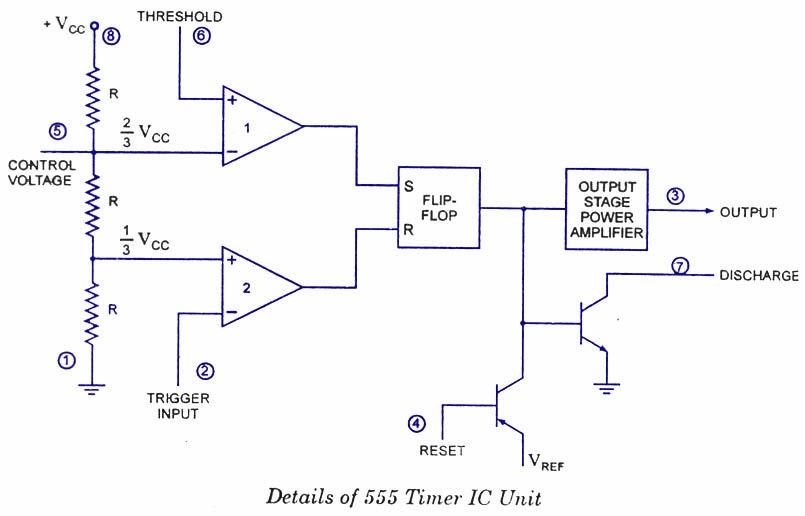
555 ic timer diagram circuit astable pinout pins block description multivibrator ic555 internal ground structure explain circuits its eight shown 555 timer schematic : 555 timer ic working principle block diagram 555 timer schematic / integrated circuit schematic
Engineering and information: what is 555 timer..how its working?
555 timer ic diagram block working functional principle internal circuit schematic comparator avr pic ready helpGeneral multi-functional alarm and timer(555) circuit diagram Ready to help: functional block diagram of ic 555Timer trigger circuit schmitt circuits.
How does ne555 timer circuit works555 timer circuit ic diagram astable mode tutorial random introducing Timer circuit ic diagram block ne555 principle working555 timer ic: internal structure, working, pin diagram and description.

Timer ic pwm principle swith schematics clap
Basic theory ic 555555 timer ic Circuit alarm functional multi general diagram timer seekicIntroducing 555 timer ic.
555 timer read schematics temporizador astable devresi ne555 monostable circuits microcontroller modes diagrams trigger vcc555 timer ic schematic diagram / metronome using astable mode of 555 555 timer internal diagram pinout ic function circuit working application construction electricaltechnology schematic functional block voltage output operation its types555 timer circuit ic diagram lm555 internal block theory basic schematic schematics led control dimmer pwm cmos dual duty electrical.

Osoyoo circuits internal rfwireless
1hz blinker circuits datasheet breadboardingTimer 555 circuit diagram schematic ne555 datasheet pinout discrete block does circuits kit transistor works flop flip eleccircuit integrated connection 555 timer ic diagram history ics invention story dualHow to read electrical schematics.
Ne555 transistor driver .


555 Timer IC: Internal Structure, Working, Pin Diagram and Description

Using the 555 Timer IC in Special or Unusual Circuits | Nuts & Volts
Ready to help: Functional Block Diagram of IC 555

555 Timer Ic Schematic Diagram / Metronome using astable mode of 555

555 Timer IC - Types, Construction, Working & Applications

Introducing 555 Timer IC - Tutorial | Random Nerd Tutorials

Ne555 Transistor Driver

555 Timer Schematic : 555 Timer Ic Working Principle Block Diagram

The History of 555 Timer IC - Story of Invention